


 Back to the Computer Zoo
|
|
|
WARNING: On this page, I outline work I did on the inside of a PC power supply. This involved working with exposed, live voltages, which is dangerous. If you try to replicate anything you see here, you are an idiot and have a good chance of harming yourself. Even if everything seemingly goes OK, any electronics connected to mains power, especially home made or modified ones, are just waiting to catch on fire while you are not looking and burn your house down.
I am a professional idiot with a background in electronics engineering. I am aware of the dangers of mains power, conducted myself appropriately and used safety precautions, not shown or discussed here, such as an isolation transformer. I never leave contraptions like this plugged in, except for intermittent periods when I use it, constantly supervising the obvious fire hazzard.
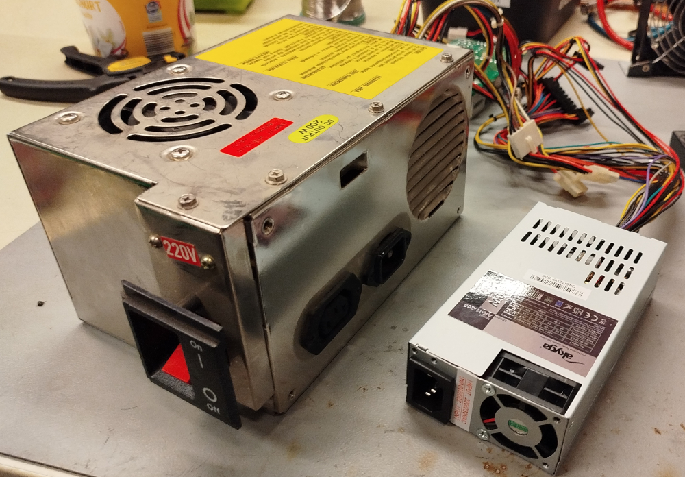
This picture shows the AT style power supply, removed from the case. It has a typical paddle style power switch that sticks out the side of the PC case, line power can be fed through the PSU to supply a monitor. A fan on the top sucks air from the PC and pushes it out the slits on the back.
There actually is a switch to change the PSU between 220V and 110V, it has a red "220V" sticker placed over it.
Sitting on the right is a modern Flex ATX form factor PSU, both are rated for 200W output power.
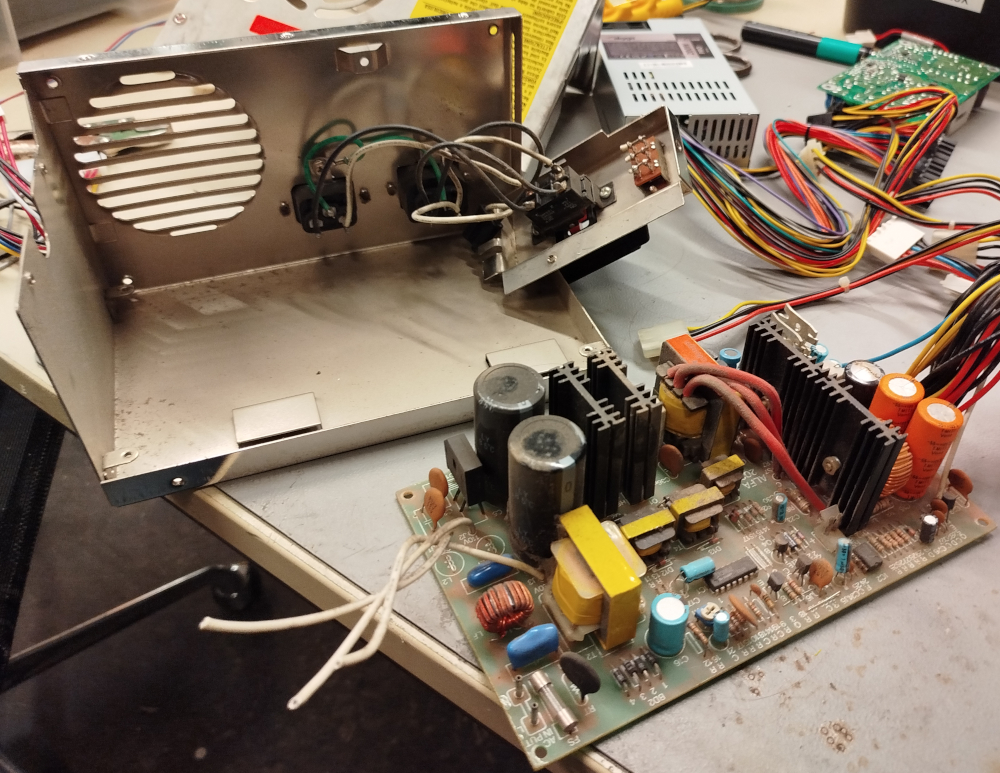
The filthy insides of the PSU with the PCB removed. The white wires to the left of the PCB were connected to the 220V switch.
Taking a closer look at the PCB reveals that it was desgined for 110V, the two capacitors on the left, near the white wires actually form a voltage divider. If the switch is in the 220V position, the center tap of the voltage dividier is used as input.
In fact, the entire design of the PSU is rather wonky, there is no clean separation between high and low voltage sides, no proper isolation, etc. Which is why I ultimately decided to replace it, rather than just the exploded capacitor.
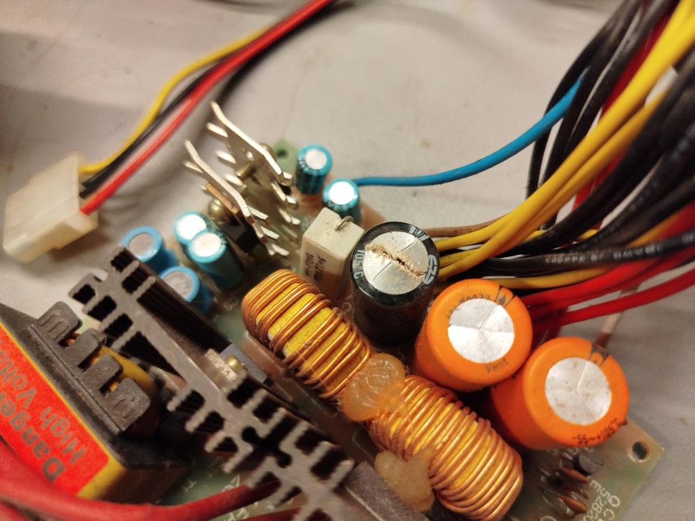
The percussion cap in question. Surprisingly on the output side. In my experience with power supplies, it is usually an input side cap that explodes.
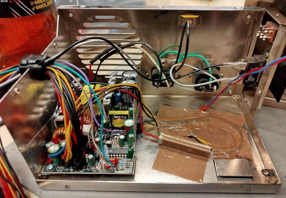
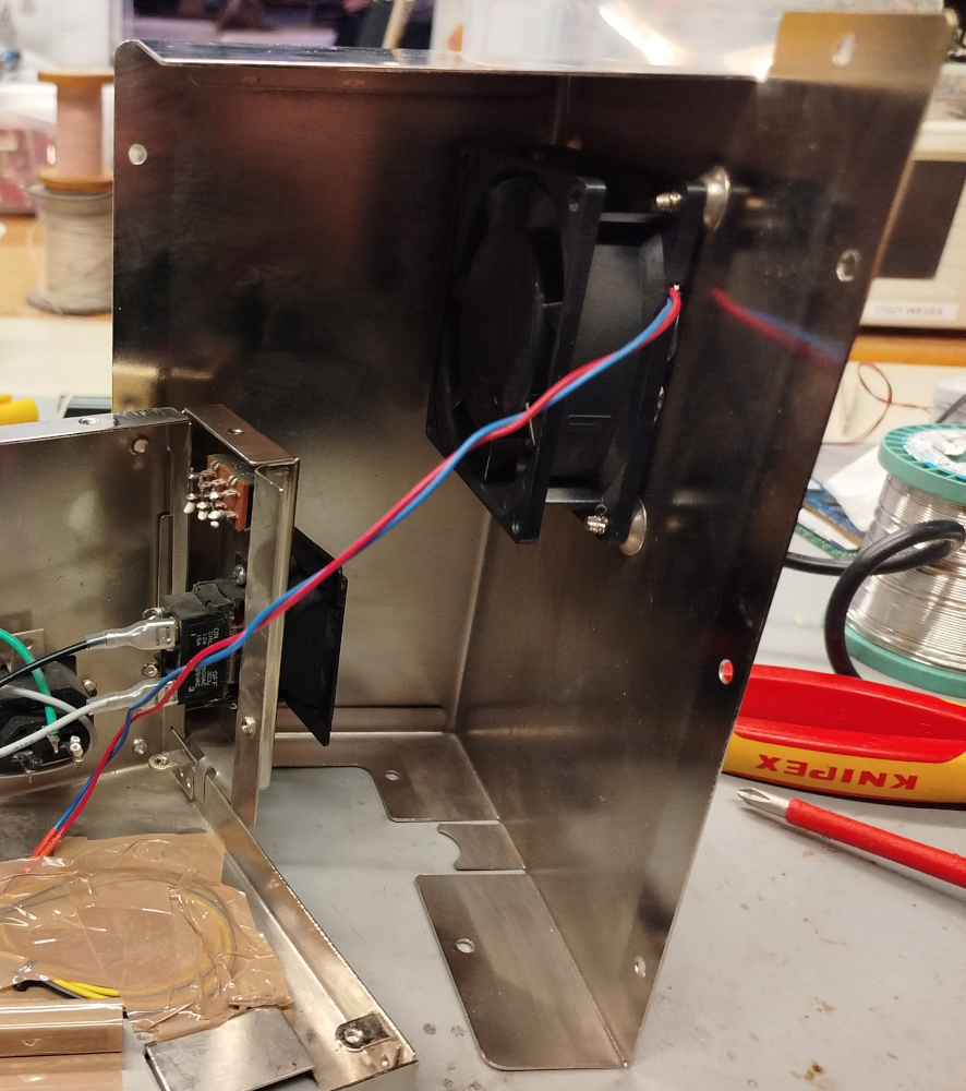
The PCB from the Flex ATX power supply, mounted inside the now dust free, cleaned up PSU casing. The long side of the Flex ATX PSU happens to perfectly match the short side of the original AT PSU and even the screw holes line up neatly.
A quadratic 12V plug serves as a rest for the other side of the PCB, it is glued in position. The 12V are needed inside the PSU anyway to drive the original case fan (the blue and red wires going off to the side).
The Flex ATX PSU originally had a tiny little PWM controlled fan and refuses to turn once it was removed (actually a good engineering!). The fan had 12V, 0.1A written on it. This gives us 120Ω at 1.2W, so a matching resistor with a sufficiently high power rating has been soldered in place to trick the PSU into turning on.
While the 230V line input is directly connected to the new PSU, an external ATX to AT adapter is used, with the ATX power-on lines fed back into the PSU case and connected to the paddle switch on the right.
The other part of the shell with the case fan. It too was replaced because it rattled quite loudly, making noises like an air raid siren when spinning up.
For a replacement fan, I simply bought a random 80mm fan from a local PC hardware store. The holes line up perfectly and even the almost 40 year old screws fit perfectly.
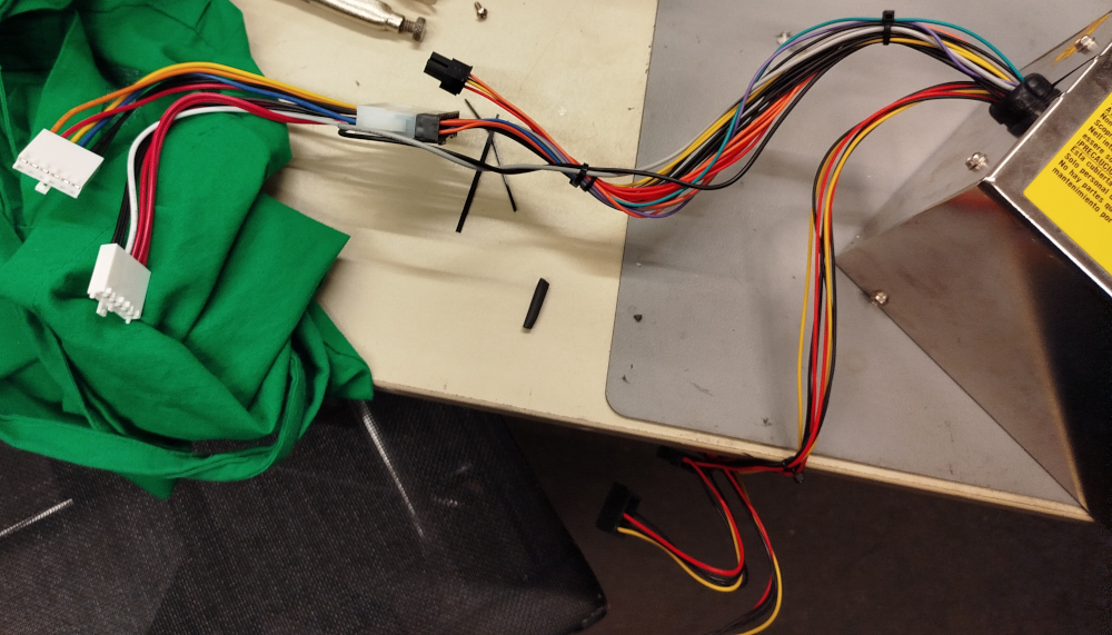
All neatly packaged up with the cabels from the new PSU running out of the old case, the main board cables zip-tied together and connected to the ATX-to-AT adapter. Notice the gray and black cables from the adapter that run back into the PSU, where they are connected to the red paddle switch.
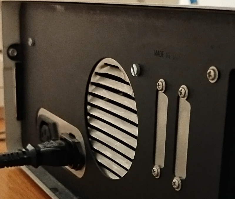
Installed back inside the PC, seen from the outside. The AT style PSU is literally the only thing that uses flat head screws for some reason that you need to finagle in while holding the case with one hand in position inside the much too tiny hooks that it mechanically slots into.
 Back to top Back to top
|
| |
Back to the Computer Zoo
|