 Back to the Computer Zoo
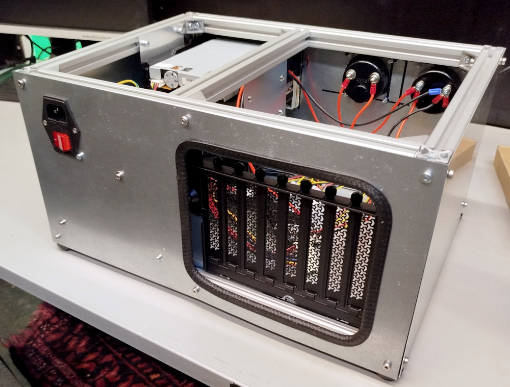
A power plug with integrated switch, fuse is mounted in the back, connecting to a 12V MEANWELL PSU, screwed to the back plate on the inside. The cage for the ISA/PCI extension cards is also mounted inside with a gaping hole in the back to allow accessed from the outside.
Edge protection from the local hardware store was added around the I/O expansion bay. The mounting bracket itself was a spare part bought from Corsair, obviously intended for some of their cases.
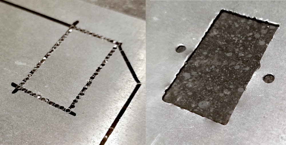
Using the tried and tested method of drilling lots of holes, prying the metal out and filing of the edges, the mounting hole for the power plug was added to the blank piece of steel.
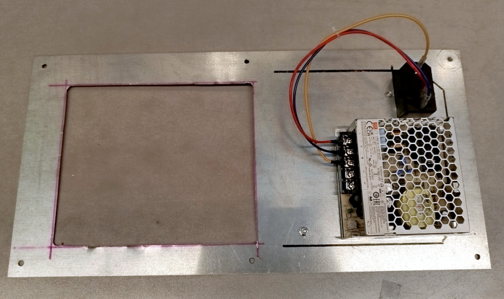
The same way, with a lot more effort, the hole for the expansion bay was added. On the right, a 12V power supply from MEANWELL was mounted and hooked up to the power plug.
WARNING: here's yet another reminder that doing literally anything with mains power is dangerous, even if you think you know what you are doing. I'm working with mains power here and this contraption theoretically allows you to touch live wires while the PC is plugged in.
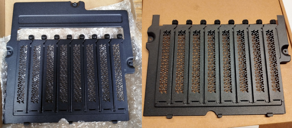
Fresh out of the package, the I/O bracket had a mounting frame at the top that I did not have space for in my design. I quickly removed it, thereby discovering that this thing is made out of some really flimsy, soft metal. Some magnesium alloy perhaps? I'm sure if you are sufficiently determined, you can cut through this with a pair of pliers.
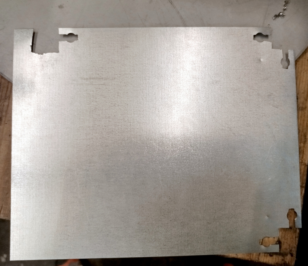
An additional piece of galvanized steel sheet metal is cut in shape for mounting inside the case.
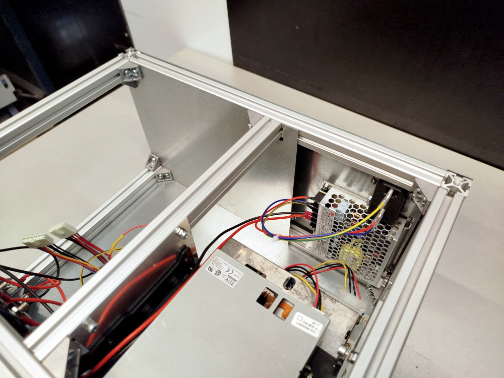
The idea is mount the I/O bracket on the inner piece of metal, leaving a 20mm gap to the outside (the width of the aluminium extrusions). Any plugs sticking out the back of the cards will be inside the gap and not protrude outside the back of the case.
In this photo, you can also see how the power supply and plug as are position inside the case, just barely peeking out from under the extrusions and the plate for the I/O shield.
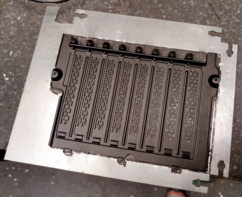
With an additional hole for the I/O bracket, it could be mounted with some counter screws from the other side.
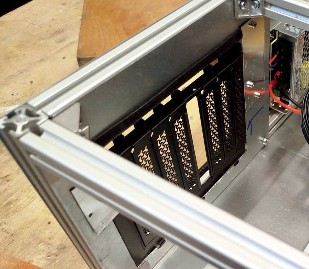
It didn't go quite to plan tough and required some additional pieces of scrap metal for mounting and supports.
You might spot a couple blue lines in this picture. This is where the AT keyboard connector from the mainboard touches the metal and where I later cut an additional hole, so the keyboard can be plugged in.
 Back to top Back to top
|
| |
Back to the Computer
Zoo
|