 Back to the Computer Zoo
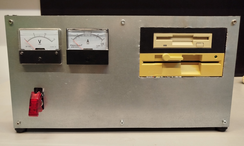
The front panel in its current form: two floppy drives, panel meters attached to the power supply and a chonky power switch with a protective cap and integrated LED.
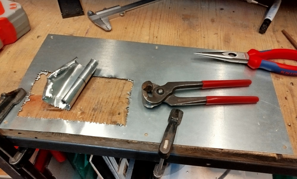
Operations started by "cutting" a hole for the floppy drives. Due to a lack of propper tools for the job, this was done by drilling a whole lot of holes with a bench drill press and then using measured violence to pry the surprisingly sturdy steel out.
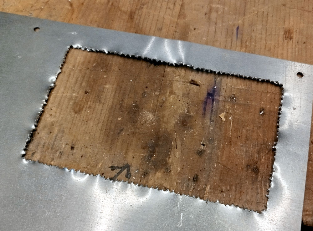
This left a jagged looking hole behind that was of roughly the right size.
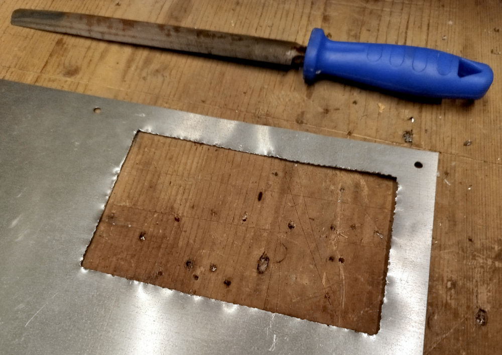
The jagged edges could be fixed with an ungodly amount of hand filing. An amount that turned to be just the beginning of the project.
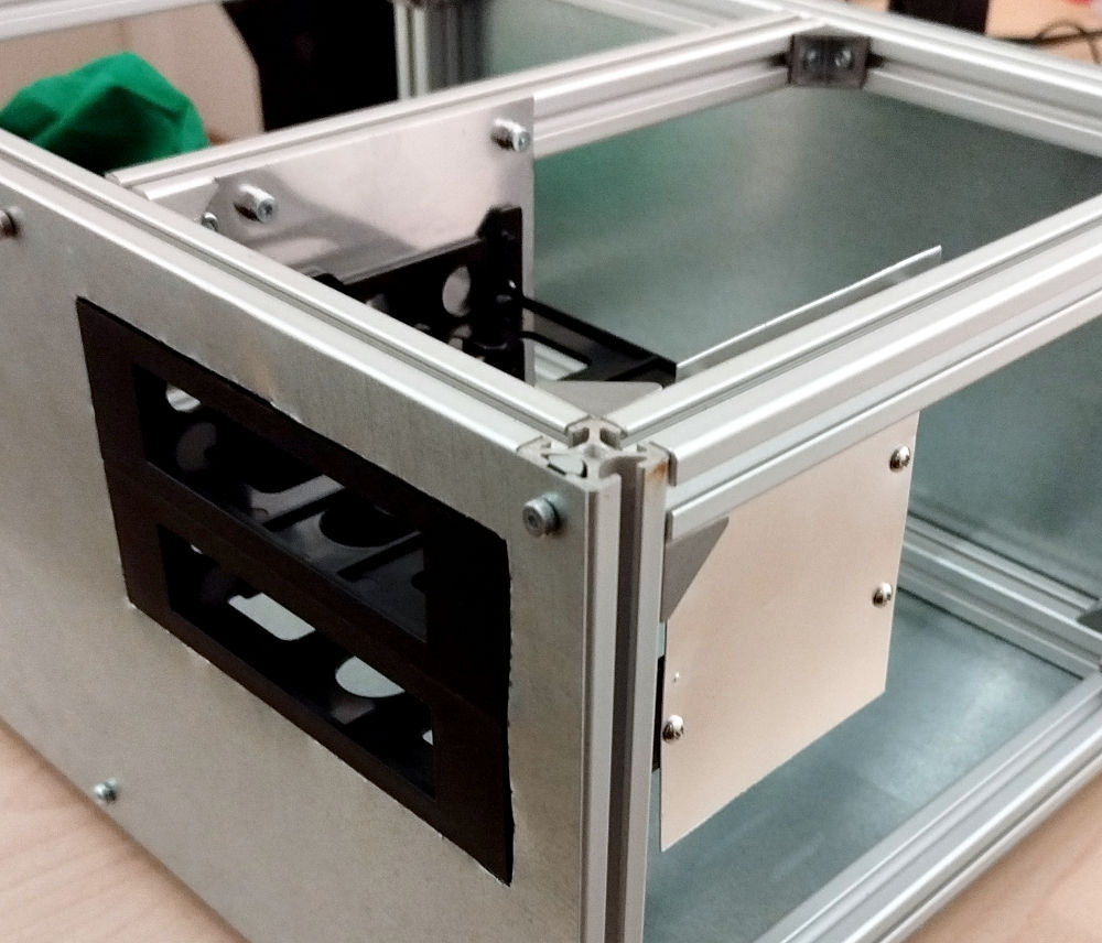
Some 3.5" to 5.25" adapters from a local store were used as stand ins for the later drives that would be mounted. An additional strut was mounted across for suspending the drives.
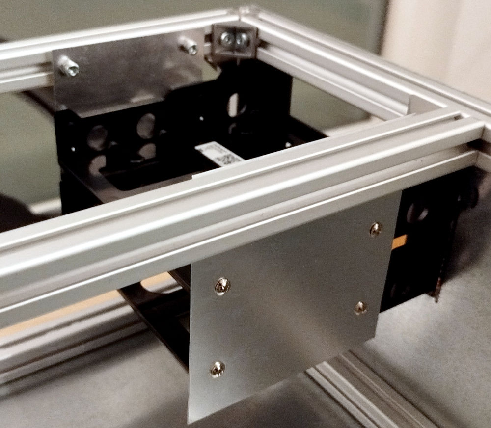
The drives are mounted to two pices of thin sheet metal that were found in a scrap metal box and had roughly the right size for the job.
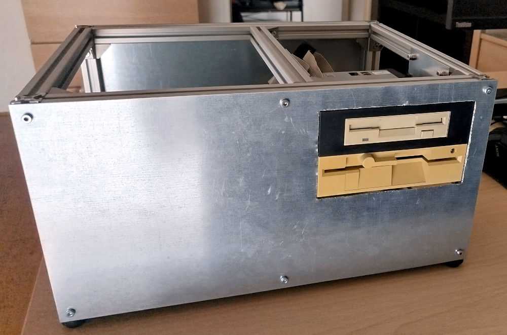
One of 3.5" adapters remained for the actual 3.5" floppy drive, the other was replaced with a 5.25" 1.2M floppy drive.
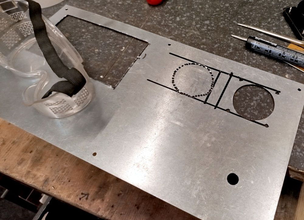
After drilling a hole for the power switch, holes were added for mounting the panel meters in pretty much the same way as the drive bay hole.
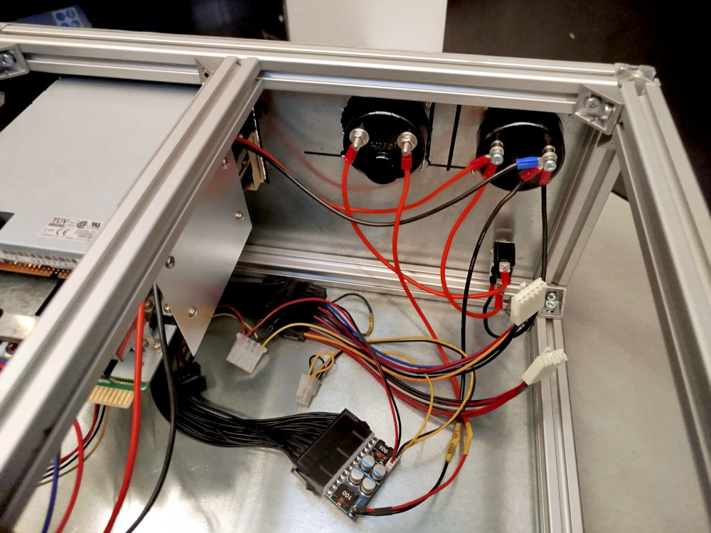
With everything wired up, a 12V power supply mounted in the back connects to the panel voltmeter, from there, a cable runs to the power switch, out the other side to the ampere meter, and from there to a DC-DC ATX power supply, rated at 60W. The ground from the power supply goes back to the ground connection on the panel voltmeter, the LED in the switch also needs its separate ground connection, also hooked up to ground on the voltmeter.
Effectively, the voltmeter shows the output from the 12V MEANWELL PSU in the back, before the power switch. The amperemeter shows the current actually flowing into the DC-DC converter when turned on (stromrichtige Messung).
An ATX to AT adapter is connected to the little DC-DC PSU, first via a 24-pin-to-20-pin ATX adapter, so this creates quite a mess of wires already.
 Back to top Back to top
|
| |
Back to the Computer
Zoo
|